
A few years ago, a friend of mine gave me a Raspberry Pi Zero for my birthday. I played around with it for a while, trying out various operating systems and what not. But with the Zero's lack of Wi-Fi and only a single micro USB slot, I could never think of anything practical to do with it.
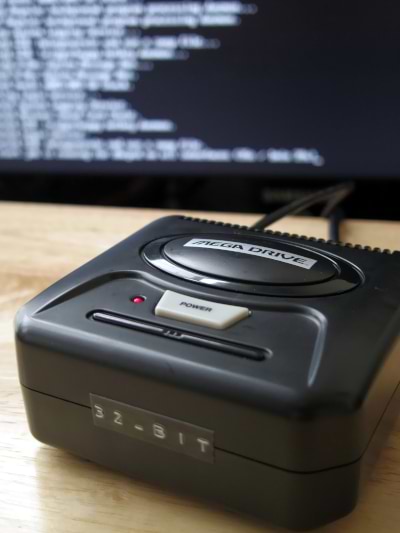
But just the other week, I finally came up with an idea: make a kind of poor man's Mega Drive mini, using the parts taken from an old Radica Mega Drive Plug and Play. My goal for this project was to preserve as much of the original console as I could, while keeping the "plug and play" functionality of the system intact. I can't honestly say this is project turned out 100% the way I wanted it to (as you'll see if you read on) but I think it came out OK in the end.
Anyway, an introduction. These old plug and play systems were manufactured by Sega Toys and distributed in the west by Radica. Released in 2004 at the tail end of the Standard definition era, each self contained unit is a system on a chip Mega Drive clone and hosts 6 classic games on a single ROM chip. It can be powered by battery or a 6v power supply. An A/V cable feeds out from the rear of the unit to connect to a TV and at the front of console a brightly coloured replica of a Mega Drive control pad is wired directly into the unit itself. It resembles a small but chunky Japanese Mega Drive II in appearance.
I was able to find mine at a flea market for just 50p, but they tend to go for anywhere between £5-£15 pounds online. They're the sort of thing you might see for sale at a much cheaper price in a charity shop/thrift store, if you're patient enough to wait for one to appear.
Here's what I suggest you'll need if you want to try making one for yourself (some of these things you may decide are optional):
Necessities
* Raspberry Pi Zero / Zero W - £5 / £12
* Micro SD Card
* 4x 2.5M nuts and bolts - £1.30
* 330 Ohm resistor - 99p
* Coloured Wires (I suggest black and red)
* Basic Soldering supplies (Iron, solder, solder sucker etc)
* Jewellers Screwdriver set
* Pi Zero Cables
Other suggested tools:
* Hot glue gun
* Dremel / Rotary Tool with attachments (sanding drum, drill bits for metal)
* File
* Craft knife
* Electrical Tape
* Dymo Label Maker
* Old Toothbrush
* Magic eraser sponge
To make the Mega Pi, it only cost me £2.29, many, many hours of the only life I'm ever going to live and a blood sacrifice to the Old Gods (honestly, no joke). I already had pretty much everything I needed except a resistor and some nuts and bolts, but it may cost you a fair amount more if you don't have a lot of this stuff. In which case, you might be better off just buying the real deal instead!
Step 1 – Prepare the Case
It felt bad to gut this poor little console (it did still work after all and I'd previously done the 8-bit guy mod on it to fix the sound) but since it only cost me 50p and they're neither rare nor expensive, I felt the sacrifice could be worth it. So go ahead and open the little guy up and remove his innards. Once you've removed all the screws, snip the wires on the battery terminals and lift everything out to one side. Next, use a jewellers flat head screwdriver to slowly and carefully lever the battery terminals out of the battery compartment. This might take a bit of force. Don't forget to bend up the retaining tabs on the inside so you can pry the terminals free (you may also need to heat up and remove some solder on the terminal tabs to be able to do this).
Now take your rotary tool and use a sanding drum to route out a hole for the USB cable (lowest setting is all you need for this). Take a look at where I chose to route the cable in the image to the right. Use a file to route a groove for the cable to sit in (I chose one of the screw holes). Clean up any rough edges if necessary with a craft knife and some sandpaper.
Next we need to drill some holes so our pi board can be securely fitted to the case. I used my dremel fitted with a 2.4mm drill bit for metal (because that's what I had), but you may wish to use something else. I can't give you good advice on how to make sure the holes line up. I used a permanent ink pen to make a mark through the pi mounting holes and I didn't get them all completely lined up, so maybe it would be smarter to measure them out first.
Finally, take your two shells and using an old toothbrush, scrub them in water and washing up liquid to remove any plastic remains. No doubt there'll be 16 years worth of grime and dust to clear out as well. If you wish, use a magic sponge on the outside of the case to buff out any scuffs (but be careful to avoid the logo)
Step 2 – Prepare the Software
I'm not going to go into much detail about loading RetroPie and ROM files onto you Pi Zero and configuring it. There are plenty of detailed guides elsewhere on how to do all this, but it should be simple enough. To do so, you'll need to find software that can write the RetroPie ISO to a Micro SD card and make it bootable (something like UNetbootin or similar). For this project, I used a slightly older version of the RetroPie operating system. Partly because it was the only way I could get the db9_gpio driver installed (more on this later) and partly because it seems a little less resource intensive on a Pi Zero than the more up-to-date versions (but this may be my imagination). It should go without saying that ROMs and emulators occupy something of a legal grey (and not so grey) area and could technically be considered piracy. To be on the safe side, it's perhaps best to load game ROMs that you already own in some way.
Step 3 – Solder Your Wires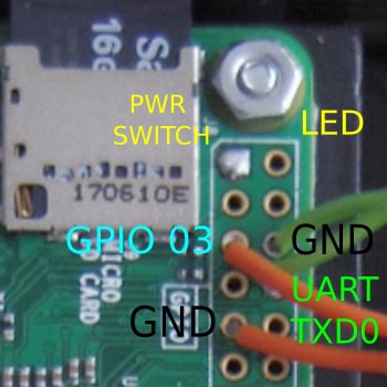 This is where things started to go a little wrong for me. Ok, so initially I had hoped to save the original controller and reuse it in the new Pi Zero powered console. I found information from here detailing the signal functions of each colour coded wire, and here, detailing how it should be wired up to the Pi GPIO. With a great deal of difficulty, I think I successfully installed the db9_gpio_rpi driver to the Pi Zero, soldered the wires to what I believed to be the right spots annnnd... Nothing. Nada. It didn't work. RetroPie couldn't detect the control pad. Nothing I tried would work. To make matters worse, I found that the wires didn't even have the length to stretch to the GPIO and also fit back into the case (soldering the wires to a veroboard and then connecting that up to the Pi GPIO is a better way to go about things). I guess it's possible that many of my software difficulties would've been a lot easier to resolve if I'd had a Pi Zero W with easy access to the Internet for this project. For all I know, I may have wired the pad up correctly after all and it was my inability to properly install the driver that was the problem (I'm no Linux power user. If it can't be downloaded from a repository, forget it).
Anyway, I abandoned hope for the time being of reusing the old controller and moved on to at least getting the power button and LED connected up. But even this didn't exactly go smoothly for me. First, prepare your wires. I suggest using red and black wires for live and ground respectively but I just used colours of wire I already had (green for ground and orange for live). I still managed to mess that up, mistakenly using all green wires for the LED and all orange for the power button. For the LED ground wire, you'll also need to solder in a resistor so that the LED doesn't pull more current than it should and quickly burn itself out. I used a 330 Ohm resistor but I think the circuit in the original Radica Mega Drive used a 270 Ohm one. This guide here explains how to wire things up to the Pi and get it all working. Note that we use the UART TXD0 GPIO here, which is a GPIO we would've needed for a fire button had we been successful in connecting our control pad. I'm unsure if it could be used for both of these purposes.
Unfortunately, I decided to wire up the LED using solid core wire. DON'T do this because it was a mistake. Had this been a high quality double sided circuit board, it would have worked just fine, but this is a low quality single sided board and the copper traces ripped away under the stress in no time at all. In the end, I soldered the wires directly to the LED itself. As far as connecting up the Power button, I think it's just a simple case of wiring it all together to complete the circuit. You'll also need to navigate to the pi boot folder and add the line "dtoverlay=gpio-shutdown" to the /boot/config.txt file to make it work (see this guide for more detail).
Curiously, it only seems to wake the Pi up and doesn't actually shut it down. I'm not sure why, but maybe it's something to do with the fact that it's a latch switch and not a momentary one. Or maybe because I used a different ground to the one specified in the guide (would that even make a difference? I didn't think it would matter). I don't know, but I'm not too concerned. Practically speaking, I'll be shutting the console down via RetroPie anyway. There are other ways of connecting up a power button, but they all seem to involve Python and like I said earlier, I had no way to easily install anything and Python is not included in RetroPie.
Step 4 – Put It All Together By far the most difficult part of this step was fitting the Pi to the case with the nuts and bolts. It's fiddly and time consuming, but eventually I was able to get it securely in place. I also had to widen two of the holes with a file to better accommodate the screw heads (the Pi Zero is just slightly too long to fit perfectly within the dimensions of the case that we're installing it into). I realised when I first tried to put the two shells together that it wasn't possible to close the case. Turns out both the prodigious amount hot glue that I'd used to secure the wires and the plastic casing around the USB cables were conspiring together to ruin my day. It was time for some surgery. I used a craft knife to very carefully shave down the globs of hot glue and the plastic casing on the wires. And when I say "very carefully", I mean I managed to slice my fingers open in two places. So the Dark Lord's blood lust is sated for another 30 seconds or so. I won't be peeling any oranges for a day or two, I can tell you that.
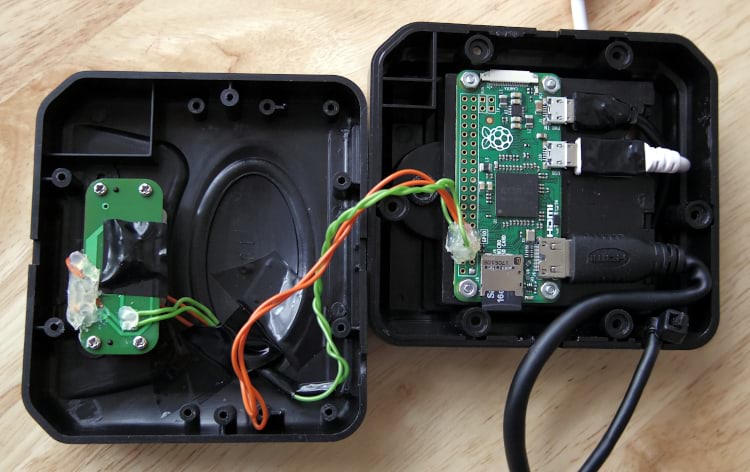
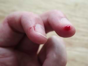 Look below to see what it looks like fully assembled. If you look carefully, you can still see evidence of my failed attempt to solder the original control pad to the Pi's GPIO and that I broke the delicate plastic retaining thingamajig meant to hold a Pi Zero camera in place (No big deal. This Pi will be in here now till it dies). PROTIP: It's always easier to solder wires and components to a circuit board than it is to desolder them. So think very carefully before you go ahead with any soldering (this is a lesson I fail to learn time and time again). You can also see where the pads ripped away on the power and LED board. Mistakes aside, it looks pretty neat and tidy. As you can see, I used a cable tie to add stress relief to the power cable. You may wish to add one to the HDMI cable, but it's in there pretty solid and I didn't think it needed one. I also covered up any exposed metal with electrical tape to prevent any potential shorts.
In the time honoured tradition of dodgy soldering, you may wish to encase your handiwork under a blob of hot snot like I did. It looks pretty ugly, but I think it's an essential step if you don't want wires flapping about and coming lose when you try putting the thing together (yes, this happened to me. More than once). As I said earlier, don't go nuts with this stuff or you'll have to shave it down to be able to fit the case back together again. Once is was all snugly closed up, for a finished touch I used a Dymo Label maker to make a 32-BIT label to stick over the hole where the old controller wire used to be.
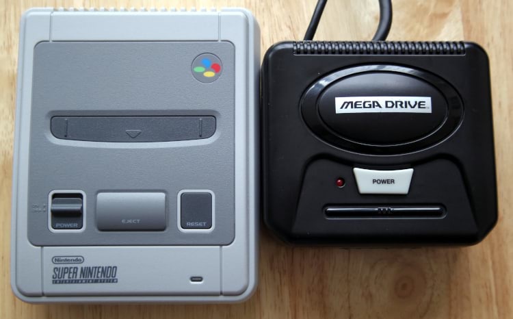
The Mega Pi next to a SNES mini for size comparison
All in all, this project ended up being a lot more time consuming, frustrating and trickier than I had initially anticipated. It also proved to be way too ambitious for me. With that said, I'm going to count this project as semi-successful, but one with room for improvement. I preserved the plug and play nature of the console and the LED and power button work more or less as they should, but I couldn't get the old controller wired up to the Pi Zero. Oh well, it's not the end of the world and I hear there are some pretty decent official Sega USB control pads available these days. I don't think the idea is 100% a lost cause, but it would need careful planning and experimentation with breadboards, header pins and jumper cables to make sure it works as it should. And using a Pi Zero W would help greatly with the software side of things. It's also obvious that space inside the case is pretty limited, so there's that to consider too. Who knows, perhaps someone else could learn from my mistakes and make it happen...
Though it might not look that way from the state of my website, I can be a bit of a perfectionist at times, and failures can irk me a little (even though I freely admit I'm by no means an expert. I just like fixing things and tinkering with electronics). It may be janky AF but it works and I learned a lot making it, which is all that really matters. While it didn't quite live up to all my hopes, there's always a degree of satisfaction to be gained from making things with your own blood, sweat and tears (quite literally in this case!), even though all I really did here is put a Pi Zero in a new case. If you want to give it a try, it's not a bad little project to get started in single board computers, electronics and learning how to solder.
+--+--+--+--+--+--+--+--+--+--+--+--+--+--+